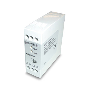
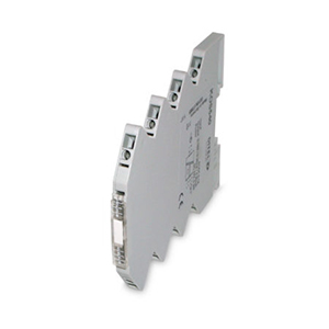
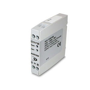
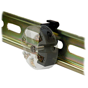
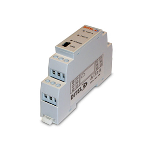
This isolator requires no user adjustment during commissioning. Minor adjustments can be made to the calibration of the device by means of the two front panel accessible calibration potentiometers. Incorrect connection in the loop will not damage the device as long as the specified maximum currents/voltages are not exceeded. If the isolator fails to operate, check loop for bad connections. Ensure enough voltage is available in the loop to power the isolator. In the unlikely event of the isolator not working, it should be returned to the supplier for repair or replacement.
KOS1010 Isolator
The KOS1010is an output loop powered analogue (4-20mA) signal isolator.
The small size enables many more units to now be installed in the same physical space.
Their high accuracy allows the addition of isolation to systems without significantly degrading the overall system performance.
The Zero and Span adjustment potentiometers can be used to remove any system errors.
Mechanical
This unit must be housed within a suitable enclosure that will provide protection from the external environment, ensuring that the stated temperature and humidity operating ranges are not exceeded. It is good practice to mount the unit away from sources of electrical noise such as switch gear and transformers. The unit enclosure is designed to snap fit onto a standard "TOP HAT" DIN Rail. To remove from rail, apply pressure at the bottom face at the back upwards the rail to release the spring clip and tip away from the top. The unit may be mounted in any orientation and stacked side by side along the rail.
Electrical
Connections to the isolator are made via screw terminals. Wire protector plates are provided inside each terminal. To maintain CE compliance twisted pair (screened) cables are recommended. It is also good practice to ensure that all 4-20mA loops are grounded at a single point in the loop. Before installation, care must be taken to ensure enough voltage is available in the loop to drive the total loop load. Refer to the specifications listed for the voltage drop.
| Isolation | 500Vac (Flash test @ 1kV) (Isolation method, opto coupler / transformer) |
| Environment | BS EN61010-1 Pollution Degree 2; Installation Cat II; Class I |
| Ambient | 0-70ºC; 10-95% RH non condensing |
| Linearity | 0.05% |
| Stability | 100ppm/ºC |
| Response Time | Less than 100mS to reach 70% of final value |
| EMC Tested to | IEC 801-2 Susceptibility to E.S.D. IEC 801-3 Susceptibility to Radiated Interference IEC801-4 Susceptibility to Conducted Interference EN55022 Radiated Emissions |
| Connection | Captive Clamp Screws |
| Cable Size | MAX. 4mm2 solid / 2.5mm2 stranded |
| Case Material | Grey Polyamide |
| Flammability | UL94-VO VDE 0304 part 3, Level IIIA |
| Dimensions | 60 x 60 x 21mm (67.5 above rail) |
| Mounting | Rail DIN EN 50022-35 |
| Adjustment | Front Entry fine Zero and Span Adjustment |
Description
The KOS1010 is designed to pro
vide an isolation barrier between a field mounted 4-20mA transmitter and the process minitoring system. The isolator output is a two wire 4-20mA current sink. The KOS1010 derrives it's power from the output loop.
| INPUT | |
| Type | Two wire 4-20mA Power & Monitors Two Wire Transmitter from the loop output |
| Range | 4-20mA (25mA MAX.) |
| Protection | Current Limited |
| Tx Supply | 5-15Vdc Max. |
| MAX. Loop Volts | 35V |
| OUTPUT | |
| Type | 4-20mA Current sink reverse protected |
| Loop Drop | 5Vdc @ 20mA (with a 10V Tx drop) 6.5Vdc max. @ 20mA DC 10V max. @4mA DC |

